The original kit does not have an indicator which shows the position of the flaps as standard. You can quite easily turn your head and see the flaps directly. So strictly it doesn't need one.
Jabiru will supply, as an extra, a very basic scale and wire pointer attached to the flap motor arm which just moves mechanically to indicate the position.
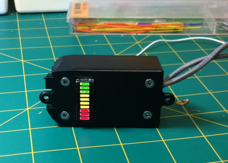
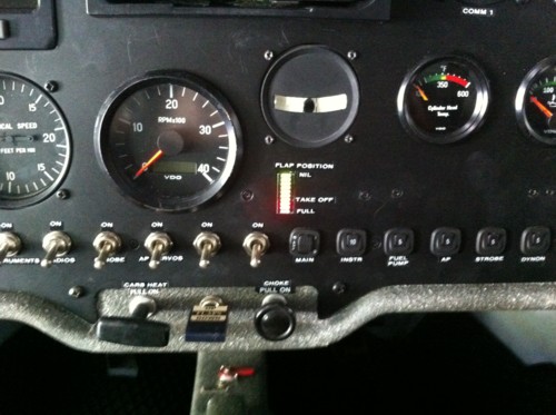
I had seen an electronic LED indicator on a video and decided to make one of those. I went through a number of versions but have finally ended up with a multicoloured LED Bar Graph Indicator which looks really nice.
It is not difficult to build if you have a little bit of electronics experience and some ability to solder.
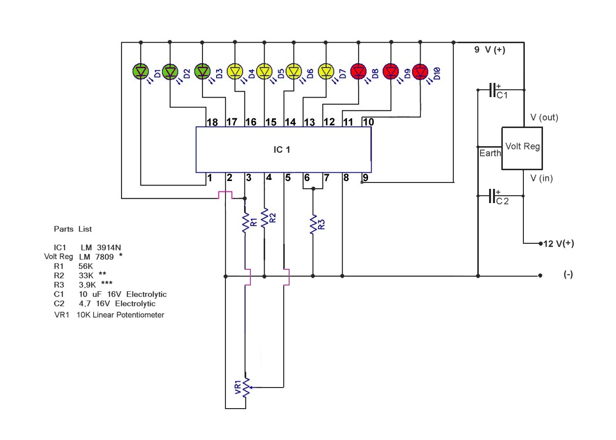
The circuit is based around an LM3914N chip which is a 10 segment LED driver chip. It is used in all sorts of circuits where a series on LEDs are used to indicate a changing scale, such as volume meters, volt meters, temperature probes and position indicators. Essentially a variable positive voltage is generated by the sensor system and that voltage applied to one pin on the chip (Pin 5). The chip turns on some number of LEDs to match the signal input.
The chip is pretty cheap ($5 or $6 from Jaycar and several other suppliers here in Australia) very robust and will work with voltages from 3 to 30 volts.
The LEDs can be 10 single LEDs but I use a unit which contains 10 LEDs in a single case which looks quite professional. These come as either single colour (red or green) or as tri-colour bars (Green, Yellow and Red in various set orders) The single colour ones are cheap ($ 1.50 to $5.00) and can be found in many places (again Jaycar has the red ones) though I had to order my tri-colour ones on line. ($2.50 plus postage from USA or up to $10 each from an Australian site.
The all up cost is about $40 AUS. Originally I just stuck the device to the back of a
2 1/4inch hole plug in an existing hole in the dash but in my latest version I cut a purpose sized rectangular hole in the dash panel and put the board in a small box which screws behind the dash faceplate.
The unit consists of three parts:
1. The main circuit board
2. A voltage regulator power source
3. The sensor unit
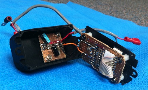
The main cuircuit and regulator boards are housed in a small plastic project box with the LED package protruding through the dash surface and the heat sink for the regulator protruding through the other back surface.
Main Circuit:
The main circuit is only slightly modified from a circuit designed as a voltage monitor for automobile batteries. The original design was found on the internet at:
See below for details on the circuit construction.
Construction
I made this on a couple of small pieces of veroboard cut to fit the project box. While it is pretty straightforward to put together there are a couple of issues.
Both chips are very robust and internally protected so if you wire them up wrongly they are likely to survive most insults, but double check all wiring before applying power.
The LM3914 is almost immune to static and can be installed without earthing straps etc. But to be safe don't handle the pins. Same with the LM7809.
You can solder the LM3914 directly to a board but if your skills are new you may be better off soldering in a socket so that the LM3914 doesn't get overheated, cross soldered etc. You can then just plug in the chip when you are happy with the soldering.
The LM7809:
This a 9 volt voltage regulator device. The family of VRs is designated LM78XX with the XX defining the voltage output. In reality you could use an LM7805 (5 Volts) instead - with probably needing to change the resistors a little to get the same results. This would result in a drop in current draw so might save a little of your battery and prolong the life of the LEDs potentially. But as I had an LM7809 already I used that.
I would not recommend using an LM7812 (12volts out) in a 12 volt aircraft because the input voltage should be 3 or more volts above the output to maintain stability.
In reality you probably could get away without a heatsink because the current draw is pretty small but then again it is enclosed in a box where heat can build up and heat is the curse of all electronics so I elected to add a metal heatsink. They are available from Jaycar in various sizes. I cut a hole in the box to allow it to protrude out for cooling.
The capacitors - These are just to reduce ripple in the current going to the LM3914 but are probably redundant. You could try it without them and if the LEDs flicker or turn on several at once then try adding C1 & 2 then. The size is not crucial but don't use ones rated for smaller voltages - they might go "bang".
You can place the LEDs some distance from the IC1 if you need to, but if the wires are more than about 15 cms there may be instability in the LEDs. If they flicker or turn on several at once a capacitor may need to be placed between pin 2 and the (+) voltage going to pin 3. I forget what size (try google for the LM3914 data sheet - there are suggested sizes there.
The Resistors
VR1 (plus R1 in series) is the sensor resistor. As it rotates the resistance changes and therefore the voltage going to pin 5 changes.
R2 - This resistor controls the range of rotation that the VR1 needs to turn to cover the full range of 10 LEDs. If you find the full range of movement of the flap motor does not equal full range of 10 LEDs lighting up try changing this resistor to something slightly bigger or smaller. I found an R2 in the range of about 27K to 39K worked.
R3 controls the brightness of the LEDs (by controlling the current through them. Be aware that the brighter they are the more current they are using and the more heat they are generating & potentially the shorter will be their life.
A note about Pin 9 on IC 1: The LM3914 will allow LEDs to light up with just one LED on at a time ("dot" mode) or a number coming on with the leading LED marking the position ("Bar" mode) All you need to do is apply the working (+) voltage to pin 9 to turn it into a bar mode or disconnect the voltage to have dot mode.
[You can actually get all sorts of modes with the addition of some extra components - flashing LEDs, Exclamation Marks and various other things. If interested Google LM3914 data sheet]
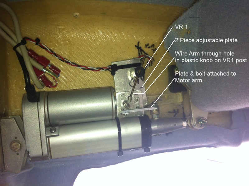
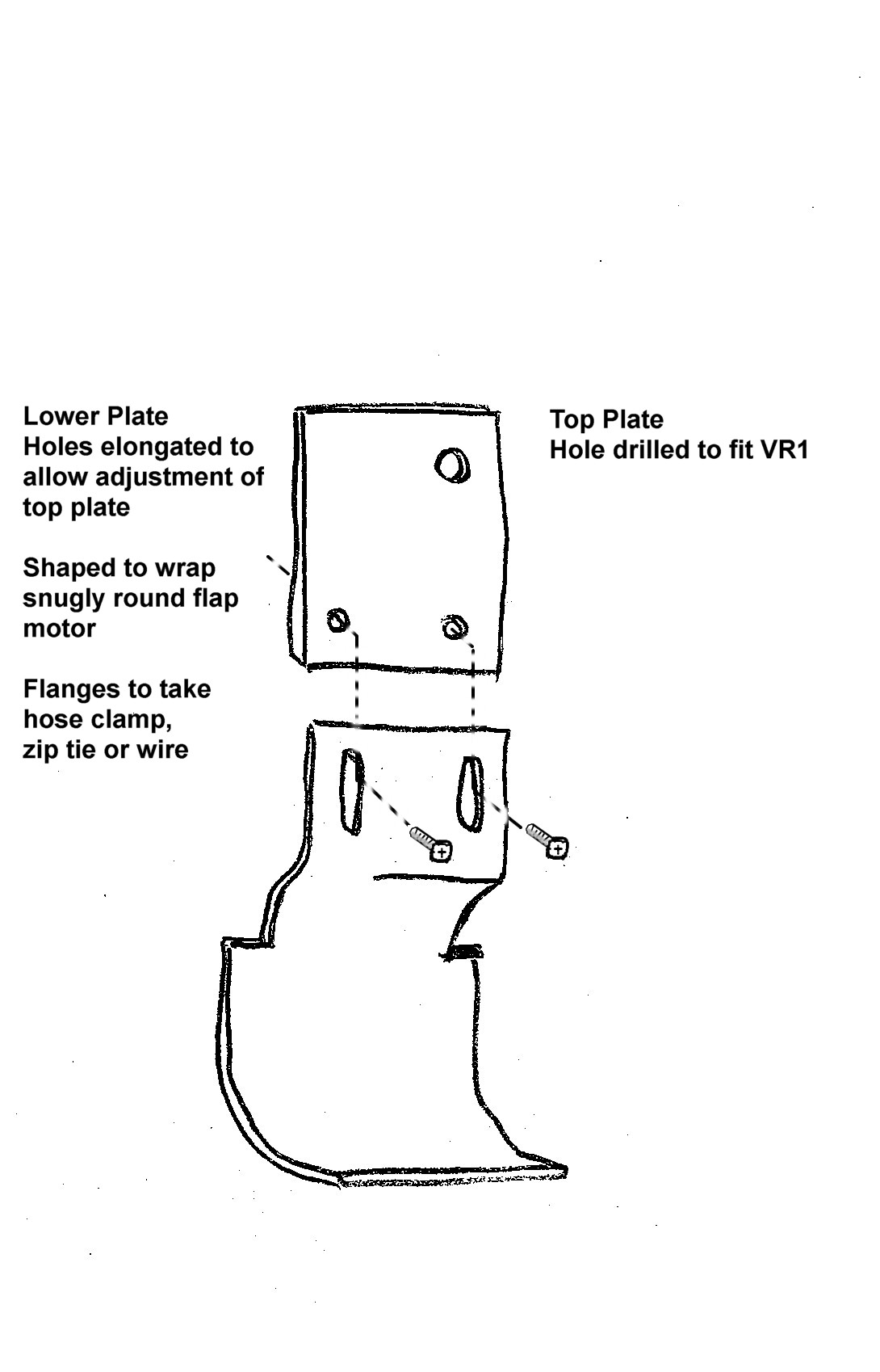
The bracket on the motor:
This is a little more complex. I made a plate of aluminium into a 2 piece bracket. VR1 is attached to the bracket which moves with the motor. As the motor arm goes in and out the whole motor actually moves up and down a little so if you fixed the VR1 to the wall of the aircraft the radius would change and thus change the displacement angle in a non linear fashion. The bracket wraps around the back and bottom of the lower section of the motor. My prototype is just zip-tied on but I have since changed it to wire.
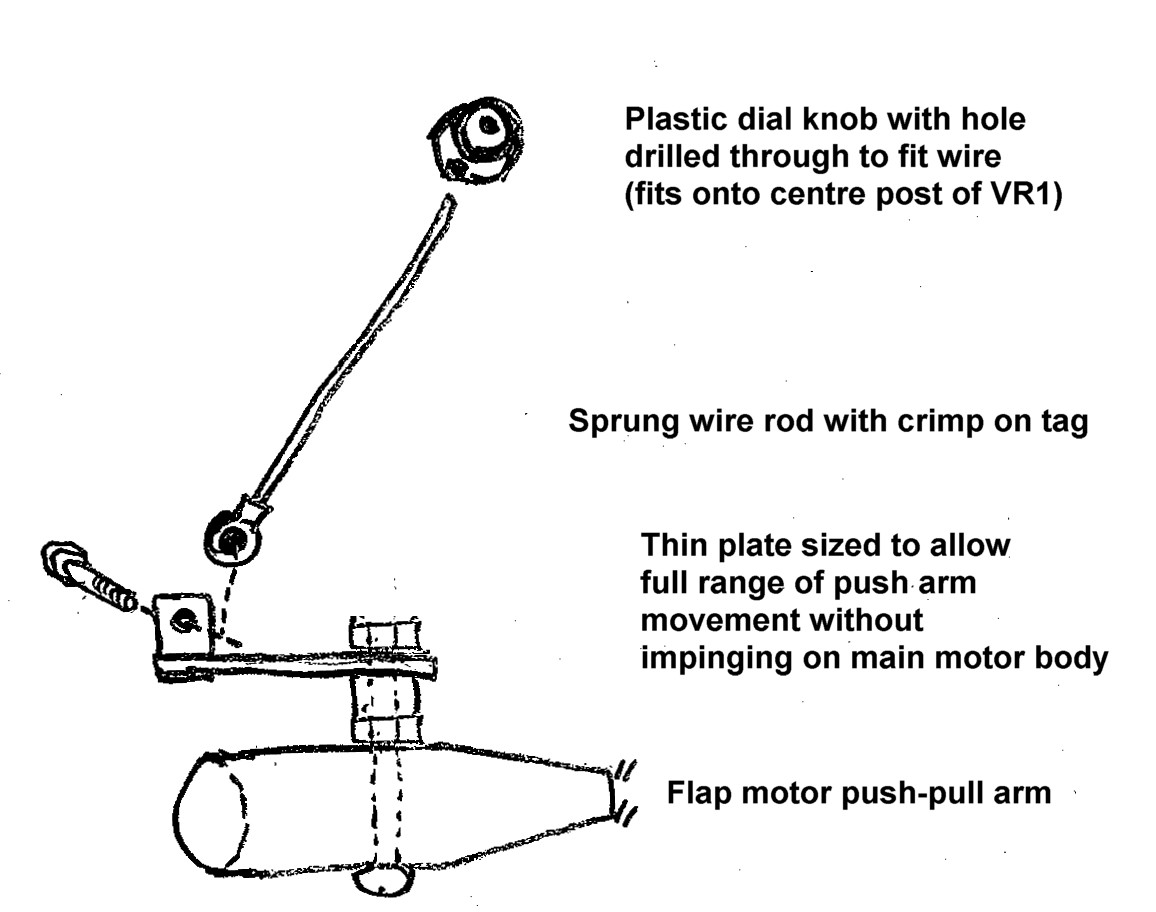
Attachment of the lever.
There is a hole in the flap motor pusher arm which can take a bolt (with a small plate attached) and bolt on it. I used a piece of heavy sprung wire as a lever. The wire goes through a hole drilled in a knob pressed onto the post of VR1.
Adjustment:
VR1 can be loosened and rotated to adjust the zero setting of VR1.
The two screws on the back plate can be loosened and the plates moved to reposition VR1.
R3 can be changed to modify the amount of rotation of the post required to cause all LEDs to turn on and off.
I actually set it up so the first LED is on in the fully retracted position and full flap gives all 10 LEDs turned on.
Power Circuit:
The voltage regulator is just a simple 9 volt regulator (LM7809) with a couple of capacitors to filter any ripples. I originally didn't have the regulator and just fed the power directly to the main board from the 12v power bus on the dash. The problem was that the input sensor in the chip is sensitive to even small increases in voltage in the power bus. When the engine is running at high revs the voltage of the bus increases by a few tenths of a volt. So it gave false readings as to the flap position. Adding the simple control of the input voltage fixed the issue.
Sensor :
The electronics of the sensor is simple - just a 10K linear variable potentiometer ( resistor). The complex bit of the sensor unit is the bracket and lever arm attaching the potentiometer to the moving arm of the flap motor.
Operation:
When the flap motor arm moves in or out the wire rod turns the potentiometer (VR1) and this changes the resistance. Three wires go to the main unit (the power, the earth wire and the wire from the centre sweep of VR1) The sweep wire feeds voltage to pin 5 of the chip and the chip turns on LEDs as appropriate.