The biggest task was to work out how to install the servos and then make brackets for them.
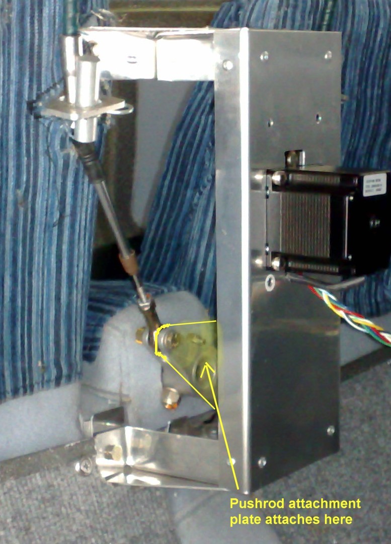
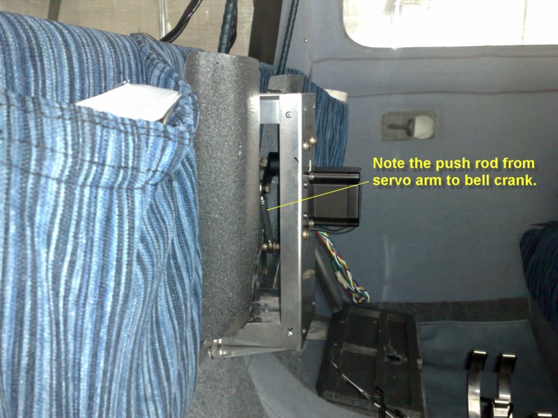
I decided to install the roll servo first, get it working and get the dash back in so I could go flying again. The pitch servo could go in later, once I was back in the air. The usual position for installing the roll servo in Jabirus is somewhere near the aileron cable connection/bellcrank at the back of the centre console. A push rod is connected from the servo rotating arm to the bellcrank. It only needs one push rod.
I had seen another Jabiru with the servo bolted to the floor and the push rod extending upwards but that posed a problem for me. I already had enclosed lockers in the space under the back half of the front seats and having the servo on the floor would require me removing a locker. It also meant I would have rear passenger's foot space decreased. I hunted around the internet and found some images of a servo installed the opposite way. That is, above the bellcrank with the push rod going down. Unfortunately the images didn't really show how it was attached so I still had to design and fabricate the bracket. After several attempts and advice from other builders I settled on the current model, I have a distinct advantage of having a good friend/fellow builder who has a metalwork shop in his backyard shed and we fabricated a flash set of brackets (one for the roll servo and one for the pitch servo when I get round to installing it.)
Basically the roll servo bracket system consists of a frame which screws into threaded inserts ( 4 mm "Nut Serts" - which are a kind of internally threaded "Pop" rivet) which I installed in the seat back. The bottom of the bracket simply utilizes the existing bolts that hold the bracket for aileron bellcrank travel stops.
The push rod connects to the bellcrank by a triangular aluminium plate which fits onto the bellcrank. The only complex part of this was working out the position for the hole in the plate and the length of the pushrod so it didn't cross "overcentre" on the servo rotating arm. This did take quite a bit of trial and error as there were two conflicting issues. Firstly the pushrod could not go anywhere near the servo rotating arm or post in it's travel (and according to the servo instructions had to not have more than 105 degrees of arc. ) But at the same time the normal range of movement of the joystick could not be limited either. The normal movement is quite a bit more than 105 degrees, so that caused some difficulty.
The final answer was to make a triangular plate with the hole for the pushrod bolt closer to the bellcrank centre.
The electrical connections were fairly simple but required the time and effort to install them. Essentially it requires fabricating a loom from the AP 74 to the D-180, a loom from the AP-74 to the servos and a couple of wires to a disconnect switch on the joystick. Fairly basic wiring so no big deal. Once the wires were run and connected the calibrating and setup could be done. Once turned on the Dynon detects the servos and the AP 74 and initialzes them almost automatically. The calibration and test sequence is easily followed - step by step from the screen. I did have some concerns in my initial calibration. The Dynon asks you to move the joystick to certain positions and click the disconnect button. Once done it gets you to run a test where the servo moves the joystick, supposedly, back to the same positions where you clicked the button.
Mine however only travelled back about half the distance in the tests. I spent several hours recalibrating, rechecking everything, re initiallizing etc with no positive result. Emailing Dynon, on their support forum, only came back with the response that it should go back to the full range positions.
Anyway, I recalibrated and tested everything and same result. I decided to see if it would go further if I actually used the AP rather just used the test mode. So I turned it on and taxied round in circles and the servo pushed the joystick right to the stops. It seemed it had limited travel in test mode but in "real" mode it worked fine.
The next phase was to do a few set ups to test and check manual over-powering the system and various other things. The default limits on mine proved to be just right for me so they all remained pretty much as they were.
The same applied to the flying set up that followed. The default sensitivities and rates of turn etc were pretty much spot on requiring minimal adjustments.
The AP is fairly sensitive and does not produce much "hunting" while following a track. I have found it hunts a bit while in track hold and GPS Nav modes, when there is a cross wind. This causes the aircraft to drift downwind and the AP then picks that up and hunts back onto track and then repeats the scenario. The hunting is barely noticible so I am very happy with that.
I did a recalibrate after some time and I seem to have fixed the hunting. It now holds very well without obvious hunting at all.
Crossing waypoints:
It does have one problem though. If I am using the GPS Nav mode and I arrive at a waypoint the AP/GPS doesn't do anything about changing track until you pass over the waypoint. It then realizes it is "off" the new track and it turns and tries to get back on the new track. When I first tried this it was a fairly brisk roll. This means a steep turn (although limited by the maximum bank angle set in my initial setup). It then crosses the track, realizes it has crossed the track and re-turns toward the track in ever decreasing small turns till it is back on track. That is both uncomfortable and time & fuel consuming. When I did the second recalibration I spent a lot more time and got it so as the turns are acceptably slow and smooth. It now comes onto the new track with minimal hunting so I can live with that.
I was under the impression the AP had an "Anticipate Mode" - where at some point prior to reaching the waypoint it could make some calculations and do a smooth turn toward the new track and line up smoothly on the new heading. But unfortunately it seems that while the AP can do that, it requires a much more complex GPS than my Garmin 296. So if I want to anticipate the turn I am limited to letting the AP fly until I get close to the waypont and then take over by hand, fly the turn and then let the AP take over again once out of the turn. Not a big deal but it would have been nice to have a complete system. It will still fly a complete navigation route but it is a bit rough at the turns.
When I used to hear people talking about having autopilots I used to think it was sacrilege. "Why bother flying at all".
But after a few long trips I began to see the sense in having another set of hands to hold things when I had to change maps or other reference material , plan a diversion or just stuff like pour a cup of tea or take a photo. The seeds of having an autopilot were sown and rapidly grew.
The first decision was, "What brand"?
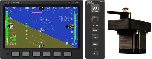
It was really a no-brainer. Dynon Avionics (who made my D 180 Flight Dek EFIS) also make an autopilot system, which is run by the D-180. What's more the software was already installed on my D-180. The Autopilot (AP) could be completed by as little as adding one servo - for a simple roll servo (and use the D-180 screen to control the AP) or go the whole hog and add a roll servo, a pitch servo and a seperate control panel (the AP 74) in the dash.
The servos were priced at US$750 each and the AP 74 for US$450. For the combined price of about US$2000 I had a complete system. This was about half the cost of the competitors so Dynon it was!
Installing the AP 74 was the biggest problem because my dash had no room at all. I already had a dash full of gizmos so installing the AP 74 meant a complete new dash. I was having problems with interference from the Dynon getting into the radios so I decided to do a complete re-wiring and design of the dash at the same time. That proved a major task and took me about two months on it's own. However it was worth it because I had the AP 74 in a good position and I got rid of the interference.
Connecting the AP 74 to the D-180 however was easy. If I had not done the rewiring it would have been an easy task.